Project 4a - Guanyou Li
Recover Homographies
The concept of recovering homographies involves finding the mathematical relationship between two images that allows us to map points from one image to the corresponding points in another. This is crucial in tasks like image stitching, perspective correction, or aligning multiple images. The transformation between two images is described by a homography matrix. Below is an explanation of the process.
The homography matrix, denoted as \( H \), is a \( 3 \times 3 \) matrix that describes how points in one image map to points in another image. Suppose we have two images with corresponding points \( (x_1, y_1) \) in the first image and \( (x_2, y_2) \) in the second image.
\[
\begin{pmatrix}
x_2 \\
y_2 \\
1
\end{pmatrix}
=
H
\begin{pmatrix}
x_1 \\
y_1 \\
1
\end{pmatrix}
\]
These points are written in homogeneous coordinates, meaning they include a third coordinate (which is typically 1) to handle perspective transformations.
To compute the homography matrix, we need at least four pairs of corresponding points between the two images. For each pair of points, we can build two equations that describe how the point in the first image transforms into the corresponding point in the second image using the unknown elements of the matrix \( H \). Each point pair gives us two equations, and we need at least 8 equations to solve for the 8 unknowns in the homography matrix.
Once we have these equations, we can represent the problem as a system of linear equations of the form:
\[
A \mathbf{h} = 0
\]
Here, \( A \) is a matrix constructed from the point pairs, and \( \mathbf{h} \) is a vector containing the elements of the homography matrix. To solve this system, we use Singular Value Decomposition (SVD), which is a technique to decompose a matrix into simpler components. SVD gives us the best solution to this system, which is the homography matrix.
Once we have the homography matrix \( H \), we can use it to transform any point from the first image to the second image by multiplying the point's homogeneous coordinates by \( H \). This allows us to "warp" the first image so that it aligns with the second image based on their corresponding points.
Warp the Images
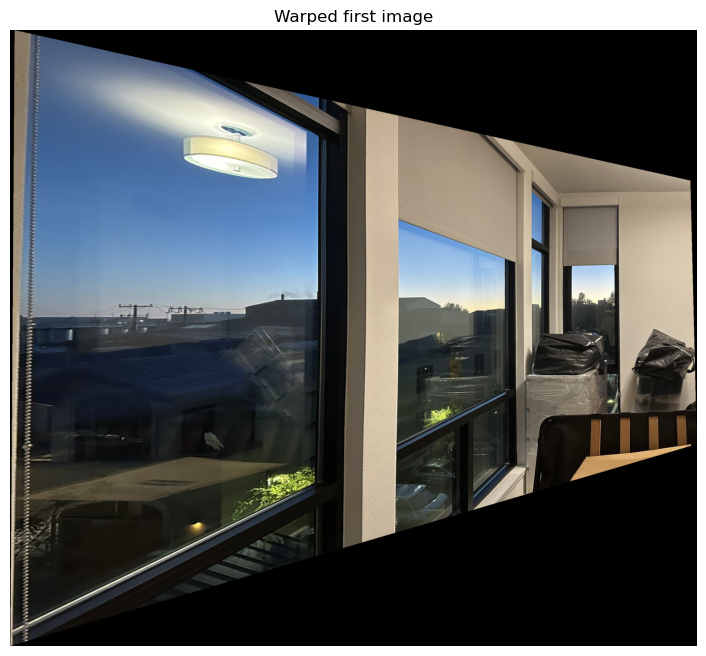
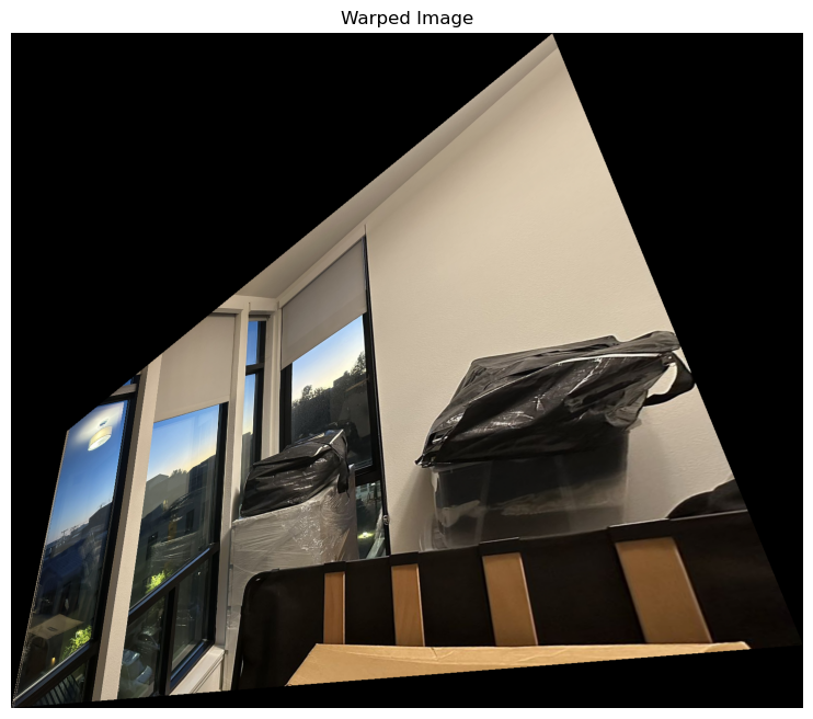
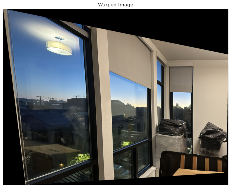
The process of warping an image involves transforming it based on a homography matrix \( H \). This transformation warps the original image to fit a new perspective, aligning it with another image or a target view. The input image is defined by its width, height, and color channels. The four corner points of the image are identified, as they define the image's boundaries. These corner points are represented in a coordinate system.
Then using the homography matrix \( H \), each of the corner points is transformed to a new location. This transformation can account for perspective shifts, rotations, scaling, or other distortions. The homography matrix applies a projective transformation to these points, which moves them from their original coordinates to new coordinates in the output image's space.
Once the corners are transformed, the system calculates the new boundaries of the warped image. The transformed corner points allow us to determine the minimum and maximum extents in both the x and y directions. A grid is created in the output image that spans from the minimum to the maximum x and y values.
To generate the final warped image, the process uses inverse mapping. For each point in the output grid, it calculates where that point originated from in the input image. This is done by applying the inverse of the homography matrix \( H^{-1} \). By doing this, each pixel in the output image is traced back to its corresponding location in the input image.
Since the coordinates derived from the inverse mapping may not directly align with integer pixel locations in the input image, the system uses interpolation to estimate pixel values. This process blends nearby pixel values from the input image to calculate the pixel intensity at fractional coordinates, ensuring a smooth and visually accurate transformation. Different channels are interpolated separately in the case of color images.
After calculating where each point in the output grid maps back to the input image, the warped image is constructed by assigning interpolated pixel values to the corresponding positions in the output image. The process ensures that all pixels in the defined output grid are filled with appropriate values from the transformed input image.
During the transformation, some areas in the output grid may not map back to valid points in the input image. A mask is applied to handle these regions, either filling them with a default value or marking them as invalid.
Image Rectification
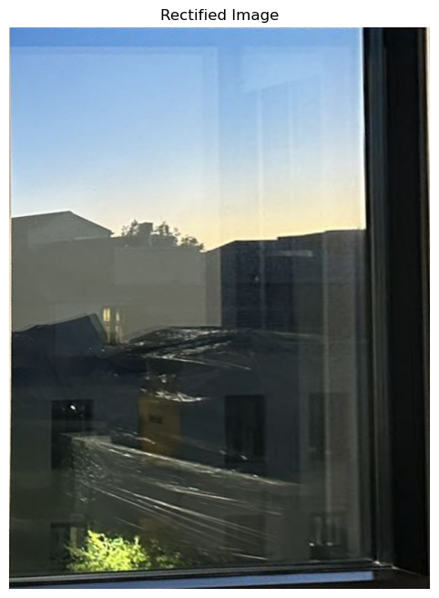
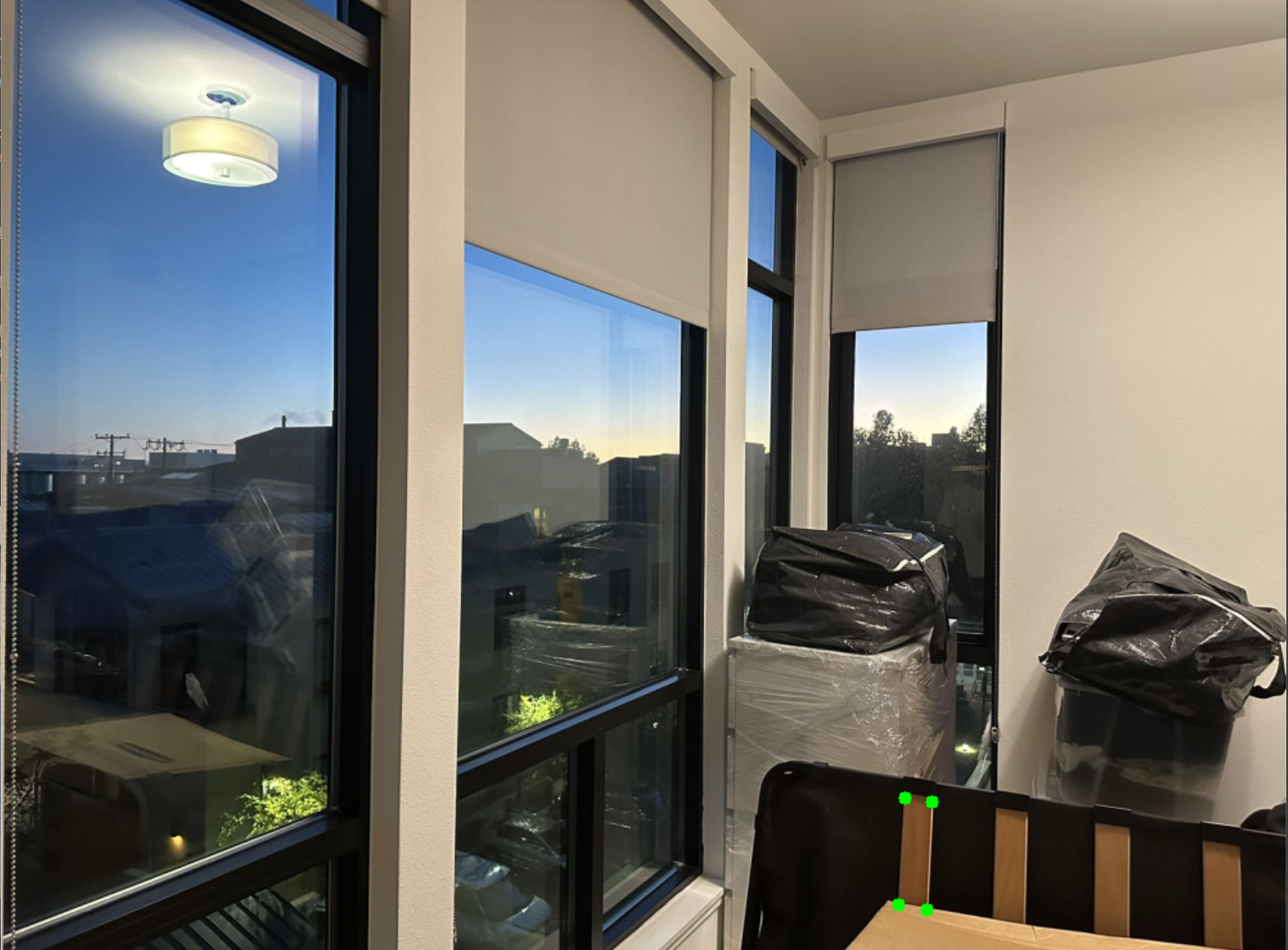
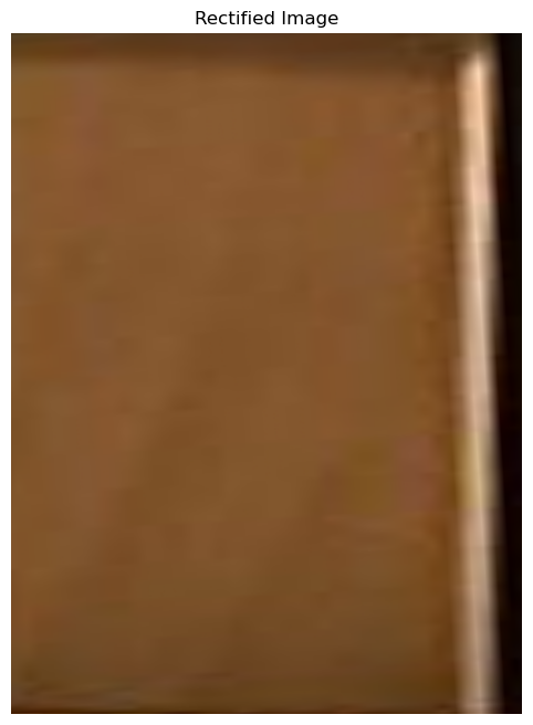
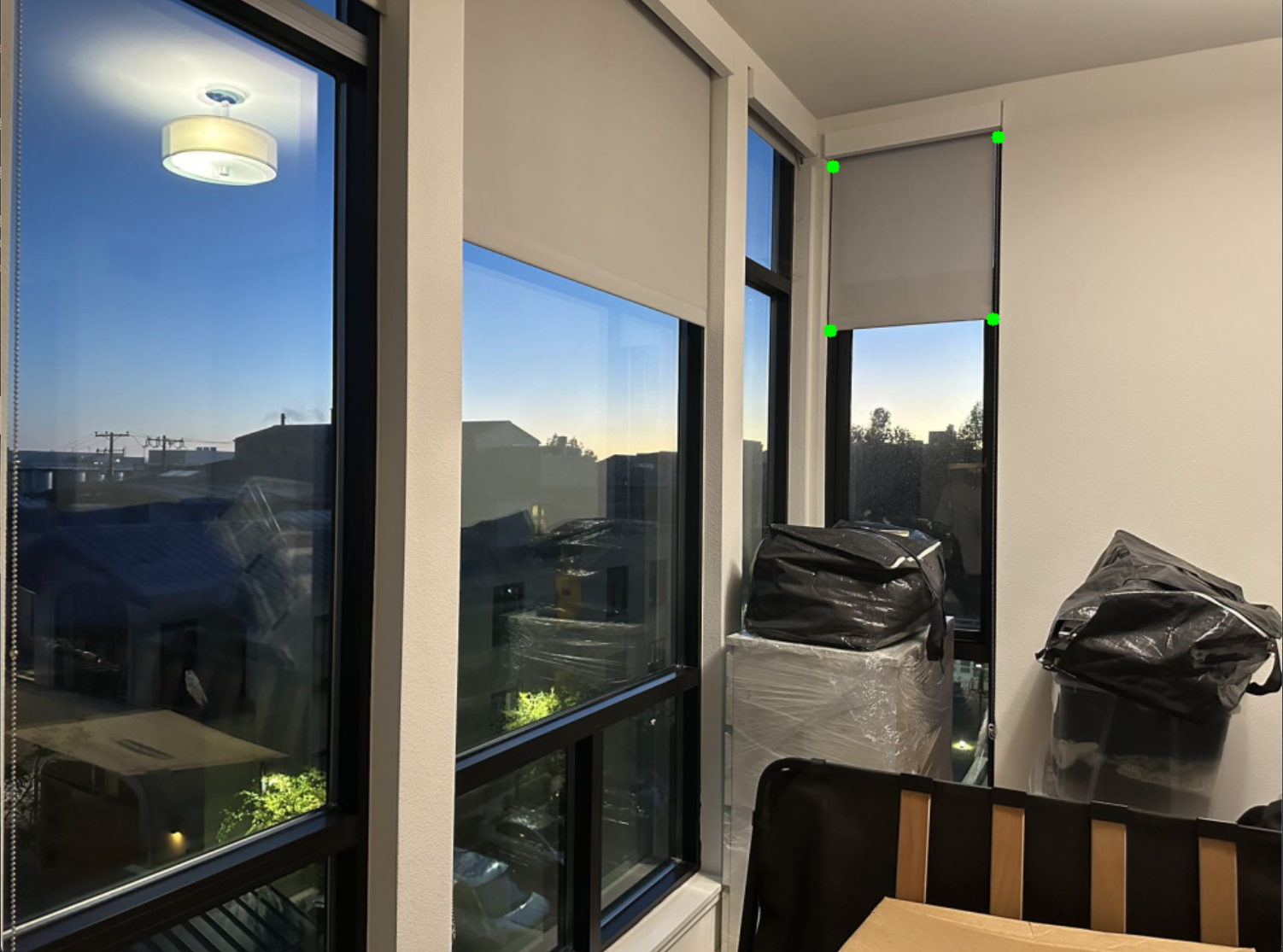
Once the points are selected, a homography matrix is calculated. This matrix defines the transformation needed to map the selected points from the original image to the corresponding points in a new, rectified view. The homography matrix is computed using the mathematical relationship between the original and destination points.
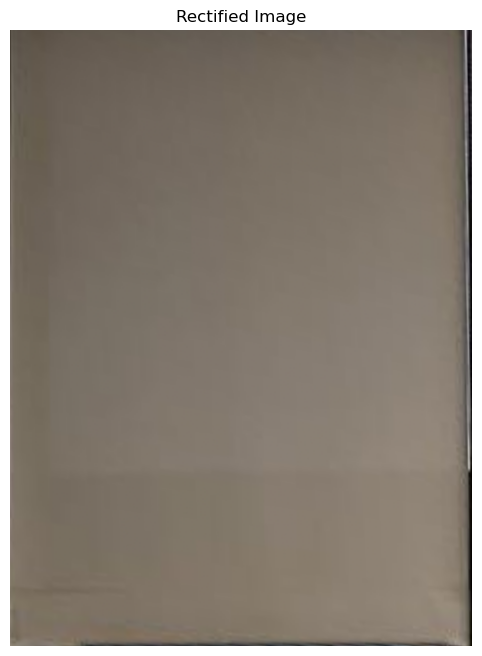
With the homography matrix calculated, the image is warped by transforming all the pixels in the original image based on the matrix. Inversely mapping each point in the output image to its corresponding point in the input image. Using interpolation to estimate pixel values for points that don't fall exactly on grid positions. The result is a rectified image where the selected points now form a perfect rectangle.
Blend the Images into a Mosaic
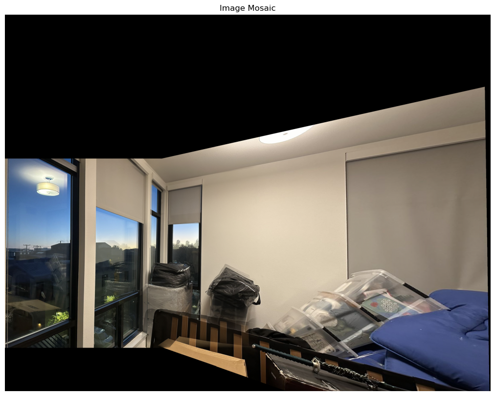
The first image is chosen as the reference image, and a homography matrix is assigned to it, indicating no transformation is needed. For each subsequent image, we need to select corresponding points in both the new image and the reference image. These points are used to calculate a homography matrix that describes how to warp the new image to align with the reference image.
To determine the size of the final mosaic (the large canvas where all images will be stitched together), the corner points of each image are transformed using their respective homographies. The minimum and maximum coordinates of these transformed corners are used to compute the bounds of the mosaic.
Each image is warped using its computed homography matrix. The warping aligns the image with the reference image and maps its pixels to the appropriate location in the mosaic. The warping uses inverse mapping, meaning each point in the output mosaic is traced back to where it came from in the original image. The pixel values are interpolated if needed to ensure smooth transitions.
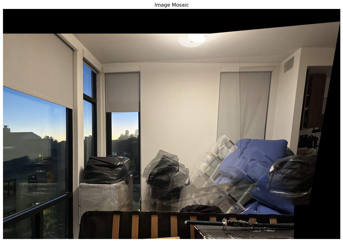
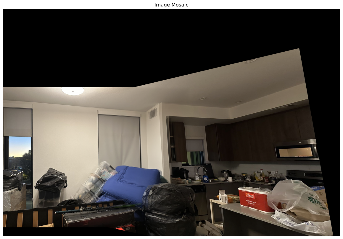
As each image is warped and placed on the mosaic, a blending process is applied to ensure smooth transitions between overlapping regions. This is achieved by computing a weight for each pixel, giving more weight to pixels near the center of an image and less weight to those near the edges. This weight is derived using a distance transform, which calculates how far each pixel is from the edge of its valid region. The further a pixel is from the edge, the higher its weight.
In areas where images overlap, the pixel values from each image are blended together based on their weights. The final color of each pixel in the mosaic is a weighted average of the corresponding pixels from the overlapping images.
To avoid division by zero in areas with no valid pixels, any pixels in the weight map that are zero are set to a small value to ensure stable blending. Once all images are warped and blended into the mosaic, the resulting pixel values are normalized and adjusted to fall within the valid range (0–255) to produce a visually accurate image.
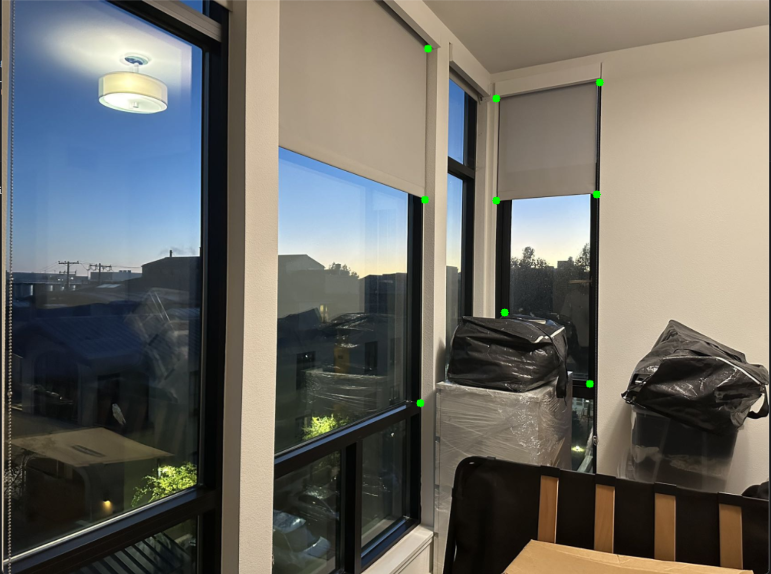
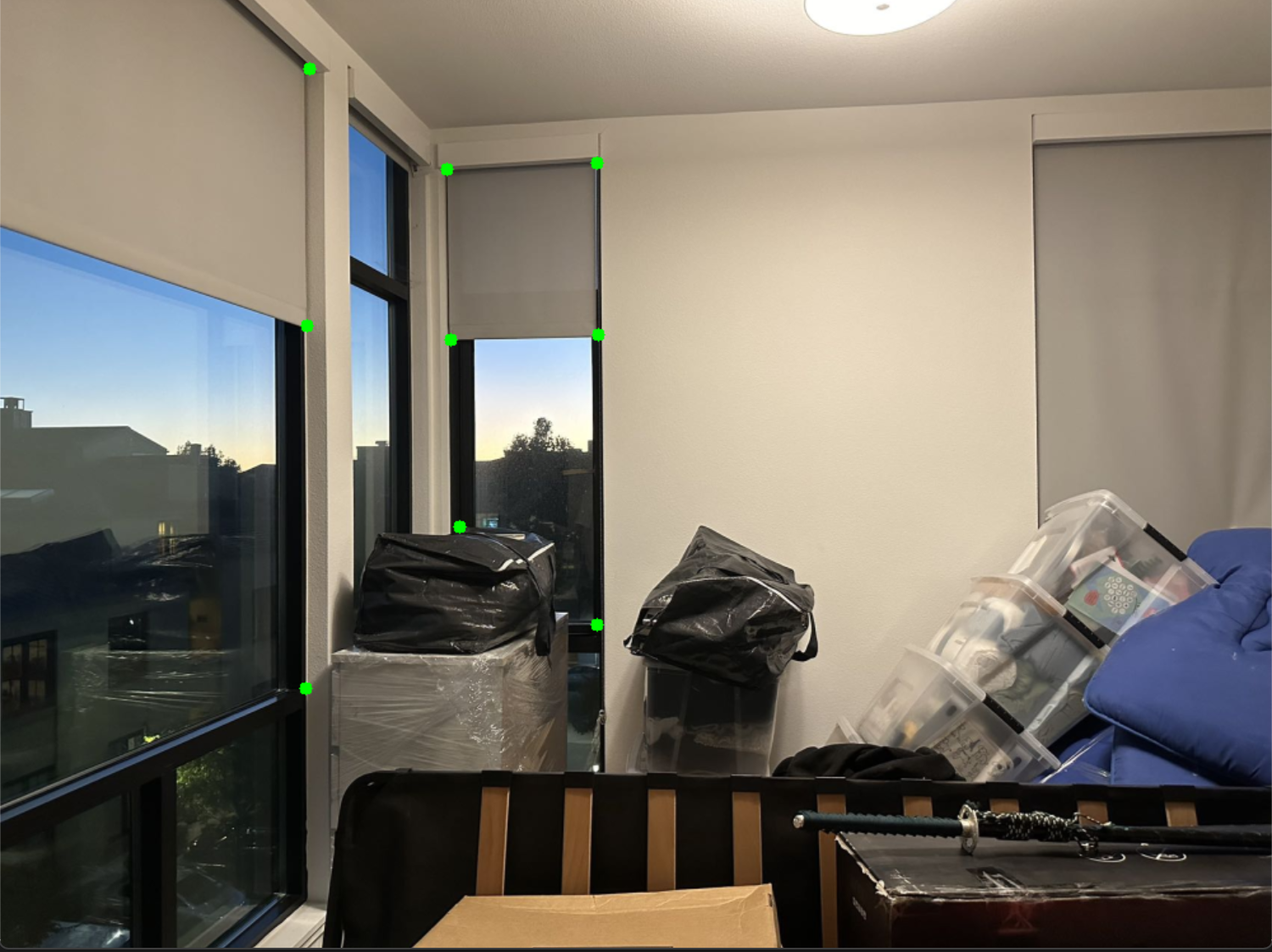
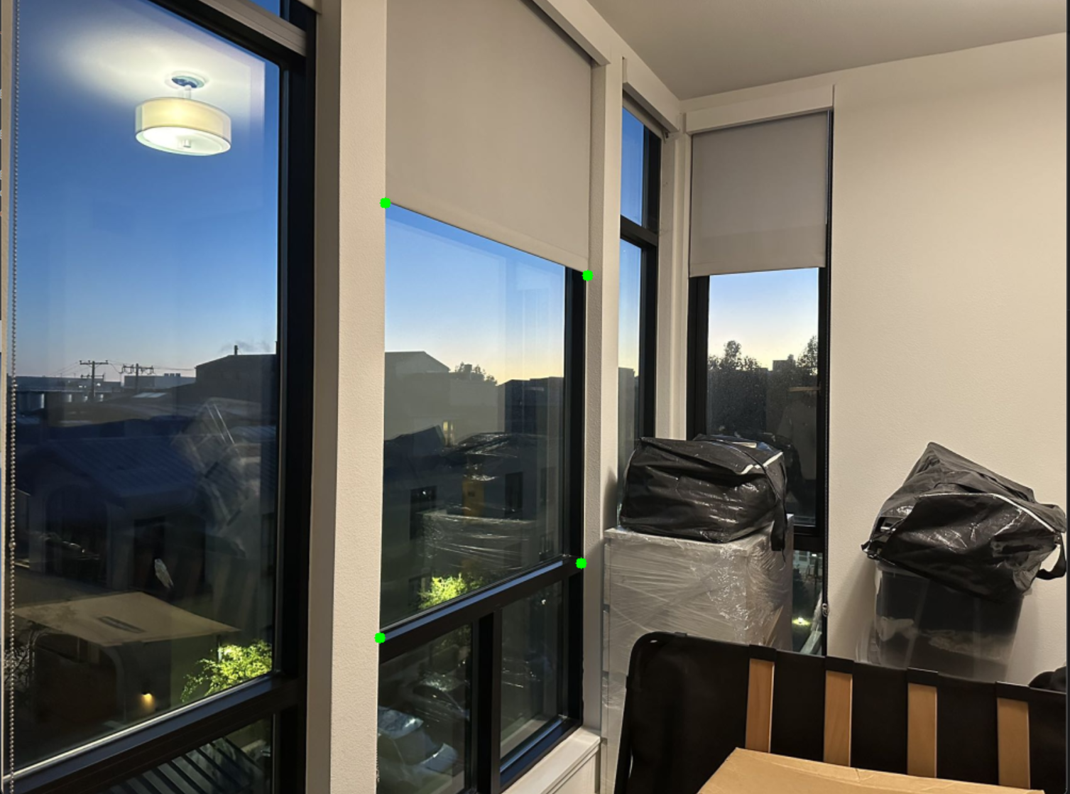
This is the three pictures I used:
This is a two-photo-formed picture (the first two):
This is a three-photo-formed picture:


